Smart Solenoid tolerance stack
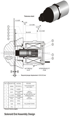
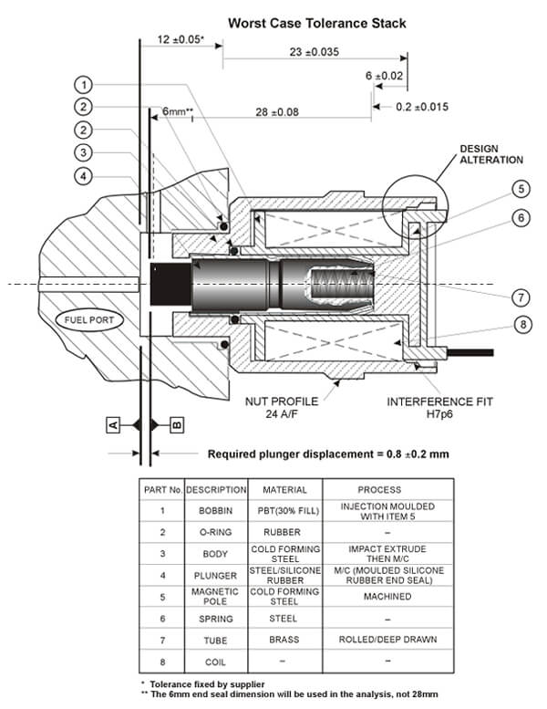
The case study briefly summarizes the analysis and redesign of the tolerance stack for a Smart Solenoid End Assembly (see Fig. 1) In carrying
out the study the company had taken tolerance stack failure severity to be a FMEA rating of four (S = 4) and the customer required a 'worst case'
analysis. The primary design requirement was to control the plunger displacement to 0.8 ± 0.2mm. Note that the tolerance on Fuel Port Block
(±0.05mm) has not been include in the analysis since it was owned by the customer.
figure 1. Tolerance stack

Analysis of the original design
The tolerance stack starts at face A on the fuel port and accumulates through the components to face B on the Plunger seal. The analysis of the
components in the tolerance stack using Tolcap is tabulated below in Table 1. The processes and materials used are shown in the Fig. 1 and in
Table 1. The pole is molded into the bobbin and the pole face is considered to be a mold related dimension. Note that the dimensional tolerance
on the Plunger is 28 ± 0.05, but the analysis will concentrate on the silicone rubber seal length of 6mm as this is molded onto the Plunger and
can be taken as a mold related dimension.
Clearly the tolerance stack is not capable as only one characteristic is acceptable when compared with the Cpk targets (Cpk(T) in Table 1) set
by the company for the stack design. The failure rate would be extremely high, given the low values of Cpk, (the associated failure cost was
calculated at over $6 million per annum against product sales revenues of around $16 million). Problems with the stack resulted mainly from
confusion with the suppliers about the capability of the impact extruded Body and Magnetic Pole, and with that of the plastic molded Bobbin.
In connection with the impact extrusions, radial capabilities had been assumed on axial dimensions! Tolcap has separate process capability
maps for each forming direction.
Given these problems a redesign was undertaken, focusing on improving tolerance capability and/or eliminating problematical parts from
the stack.
Table 1 - Tolcap results produced for the original design (Dimensions in mm)
| No. |
Description |
Process/ Material |
Dim. |
±Tol. |
Cpk(T) |
Cpk(P) |
Comment |
| 1 |
Bobbin |
Injection mold
(PBT with insert) |
22 |
0.035 |
1.38 |
0.05 |
Redesign |
| 3 |
Body |
Impact Extrusion
(Forming steel) |
3 |
0.02 |
1.38 |
0.05 |
Redesign |
| 4 |
Plunger |
Rubber molder
onto M/C plunger |
6 |
0.05 |
1.38 |
0.62 |
Redesign |
| 5 |
Magnetic Pole |
Impact Extrusion
(Forming Steel) |
8 |
0.02 |
1.38 |
0.05 |
Redesign |
| 7 |
Tube |
Deep Drawn
(Brass) |
0.2 |
0.025 |
1.38 |
4 |
Capable |
Redesign and analysis
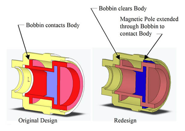
Based on the analysis results redesign solutions were generated by the design team. (See Fig.2 for one of the solutions). The redesign shown has
eliminated the Bobbin component from the stack. The Magnetic Pole (molded into the Bobbin) has been positively located against a machined step
in the Body component. Fig. 3 illustrates further the original and redesign solutions. (The body was already machined at one end to provide
location on the Fuel Port Block).
The Tolcap analysis results are tabulated in Table 2. All components are now process capable. As can be seen from Table 2 the tolerance stack is
now capable and the design can be produced with low levels of failure cost. This redesign alternative resulted in a calculated failure cost of
only $6 thousand per annum. (The additional machining of the Body was not significant in the calculations.)
Table 2 - Tolcap results for Smart Solenoid redesign
| No. |
Description |
Process/ Material |
Dim. |
±Tol. |
Cpk(T) |
Cpk(P) |
Comment |
| 1 |
Bobbin |
Injection mold
(PBT with insert) |
No longer in the tolerance stack! |
| 3 |
Body |
Impact Extrusion
(Forming steel) then machined |
23 |
0.03 |
1.38 |
2.71 |
Capable |
| 4 |
Plunger |
Rubber molder
onto M/C plunger |
6 |
0.09 |
1.38 |
0.43 |
Capable |
| 5 |
Magnetic Pole |
Machined
(Free-Cutting Steel) |
6 |
0.015 |
1.38 |
2.33 |
Capable |
| 7 |
Tube |
Deep Drawn
(Brass) |
0.2 |
0.015 |
1.38 |
3.01 |
Capable |
figure 2. A redesign solution

figure 3. Further illustrations of the solenoid original and redesign

This Case Study has been reported previously in the paper 'Process Capable Tolerancing' published by Machine Design, see Tolcap Resources. The
analysis given here has been carried with the current version of Tolcap and consequently there are some small differences in Cpk predictions and
capable tolerances for some of the components when compared with the analysis reported in Machine Design, which made use of an earlier release
of the software.
Back to the resources